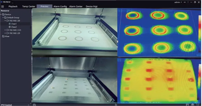
Simply put, an infrared thermal imaging camera converts the invisible infrared energy emitted by objects into a visible thermal image. The different colors on the thermal image represent the varying temperatures of the object being measured.
Infrared Thermal Camera Construction
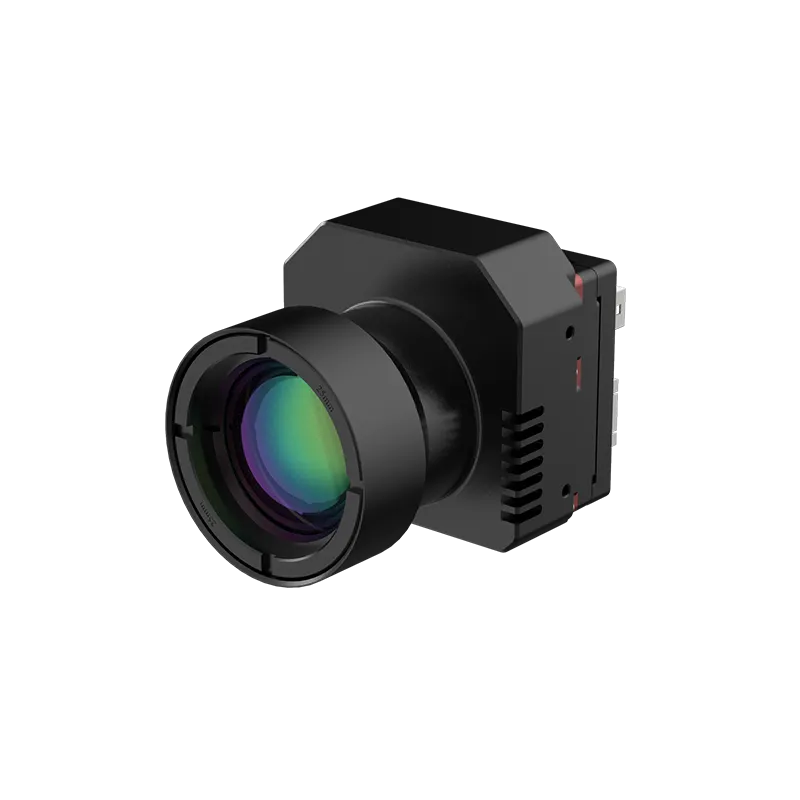
The infrared thermal camera construction is similar to a digital camera. Although they are similar, there are some differences in their construction. This article introduces the main components of an infrared thermal imaging camera to help you better understand what distinguishes it from a regular digital camera.
Infrared thermal imaging camera consists of four main parts: (1) Infrared objective lens: receives and focuses the infrared radiation emitted by the object being measured; (2) Infrared detector: converts the thermal radiation pattern into electrical signals; (3) Electronic processing units: The electrical signals are processed through various image algorithms to output an image video stream visible to the human eye, while simultaneously performing digital signal analysis on the electrical signals to output target temperature data. (4) Display screen: convert the electrical signals into a visible thermal image.

Main Components of an Infrared Thermal Camera
1. Infrared Lens (Objective Lens)
The infrared lens serves as the imaging optical component for an infrared thermal imager, and its quality directly affects the image quality, impacting the implementation and results of algorithms. A larger lens aperture enhances light-gathering capability, resulting in clearer images, which also increases its weight and cost. The focal length determines the field of view; a longer focal length extends the detection range and increases magnification, but narrows the field of view while improving image clarity.
Function of the Infrared Lens
The infrared lens filters out visible light while allowing infrared light to pass through. It separates infrared light from visible light in environments where both coexist. By adding an infrared filter, visible light is blocked to achieve a pure infrared effect.
Differences Between Infrared and Regular Lenses
The range of detectable wavelengths is different. Due to these differences in wavelength, the focal planes for visible and infrared light do not coincide.
- Visible light wavelength range: 380 – 740nm
- Infrared wavelength range: 700 nm – 1 mm
Classification
Infrared thermal imaging lenses can be classified based on their operating wavelength bands into long-wave infrared lenses, mid-wave infrared lenses, and short-wave infrared lenses.
- Long-wave infrared lenses: These operate in the wavelength band of 6 – 15 µm.
- Mid-wave infrared lenses: These operate in the wavelength band of 3 – 6 µm.
- Short-wave infrared lenses: These operate in the wavelength band of 0.75 – 3 µm.

Common Materials
In the visible light spectrum, glass is an excellent material for transmission. However, it is opaque in the mid-wave and long-wave infrared bands, so crystal materials like germanium and silicon are commonly used instead due to following reasons:
- Germanium: Known for its high hardness, good mechanical properties, and thermal conductivity, and it is insoluble in water. Its spectral transmission range is 1.8–12µm, covering the entire mid-wave and long-wave infrared bands.
Silicon: It has high hardness and is insoluble in water. Silicon offers excellent light transmission in the short-wave and mid-wave infrared bands of 1.1-9µm. It is a chemically inert material often used to make 3-5µm mid-wave infrared lenses.
To enhance transmittance, an anti-reflective coating is usually applied. These materials and coatings act like filters, limiting the wavelengths transmitted through the lens to a specific range.
Additionally, there are other materials with certain transmittance in the mid-wave and long-wave infrared bands, such as:
- Sapphire: Has a transmission band from 0.15 to 5.5μm.
- Zinc Selenide (ZnSe): Known for its uniform and consistent refractive index, it is a chemically inert material with high purity and strong environmental adaptability. It has low optical transmission loss and excellent light transmission properties, making it an ideal material for protective windows and infrared optical lenses in thermal imaging.
- Zinc Sulfide (ZnS): This material also has a uniform and consistent refractive index, offering excellent transmission performance in the 8 to 14μm long-wave infrared band. It also has good transmittance in the mid-infrared band. However, as the wavelength shifts towards the short-wave, absorption and scattering increase, with a short-wave cutoff limit at 0.35μm, which can affect infrared imaging. Compared to zinc selenide, zinc sulfide is cheaper, harder, has twice the fracture strength, and is more resistant to harsh environments, making it an ideal material for long-wave infrared lenses.
- Barium Fluoride (BaF2): Exhibits close to 90% optical transmittance over the 200–9500nm spectral range. It is typically used in cooled infrared thermal imagers. Barium fluoride is soluble in water and thus can only be used in dry environments.
- Gallium Arsenide (GaAs): Known for its high hardness, good chemical stability, and strong resistance to harsh environments. It has excellent transmittance in the mid-to-long wave infrared range (2µm—14µm). Its strong scratch resistance and low environmental requirements make it a perfect substitute for zinc selenide as a material for infrared camera lenses.
2. Infrared Detector/Thermal Sensor
Infrared detectors react to incoming infrared wavelengths and convert them into electronic signals. Based on their operating principles, infrared detectors can be classified into two types: cooled and uncooled.
Cooled infrared focal plane detectors are known for their high sensitivity, enabling them to detect finer temperature differences and operate over longer distances. They are primarily used in high-end scientific research equipment.
Uncooled infrared detectors do not require cooling systems and can operate at room temperature. They are compact, lightweight, low power consumption, long lifespan, low cost, and quick startup. Although they are less sensitive compared to cooled infrared detectors, the performance of uncooled detectors is sufficient to meet the technical needs of some scientific research equipment and most civilian applications.
Uncooled infrared detectors are mainly based on thermal sensors prepared using micro-electromechanical systems (MEMS) technology. They can be roughly divided into several types: thermopile/thermocouple, pyroelectric, optomechanical, and microbolometer. Among these, microbolometers have seen rapid technological advancement and hold the largest market share.
Microbolometer
A microbolometer utilizes the temperature-sensitive properties of thermosensitive materials’ resistivity. When these materials absorb infrared radiation, their temperature increases, causing a corresponding change in resistance. This change converts infrared radiation into an electrical signal, which is then used to generate a thermal image and detect temperature values.
Common thermosensitive materials include metal and semiconductor films:
- Metal Films: As temperature rises, the electron mobility (known as electron migration rate) in metal films decreases, leading to an increase in resistance. This phenomenon is represented by a value called the Temperature Coefficient of Resistance (TCR), which is positive for metal films. Due to their low TCR, the resistance change in metal films is not very pronounced, so they are typically used only in prototype devices rather than widely applied.
- Semiconductor Films: Semiconductor thin films: As the temperature increases, the number and mobility of charge carriers in semiconductor materials (such as vanadium oxide and amorphous silicon) also increase, leading to a decrease in resistance. Unlike metallic films, semiconductor materials have a negative TCR, which is an order of magnitude higher than that of metallic films, meaning they are more sensitive to temperature changes. Therefore, they have become the most commonly used thermosensitive materials, widely employed in devices that require precise temperature detection.
3. Electronic Processing Unit
The electronic processing unit typically comprises one or more printed circuit boards, depending on its design. These boards incorporate specialized microcircuits that handle the signal processing from the sensor and transmit it to a display, where a visual representation of temperature distribution is created. Additionally, these boards house the primary control components of the device and manage power distribution circuits.
4. Display Screen
Depending on different applications and needs, infrared thermal imagers are equipped with various types of displays to meet specific functional requirements.
Display Modes
Thermal imagers can use either black-and-white or pseudo-color displays. Black-and-white displays are typically used for basic temperature detection, providing simple thermal images. In contrast, pseudo-color displays differentiate temperature regions using colors, making temperature distribution more intuitive and easier to analyze. Generally, red, yellow, and orange indicate warmer and hotter areas, while purple, blue, and dark blue indicate cooler areas.
Resolution
The resolution of the display directly affects the clarity of the image. Common resolutions include 160 x 120, 320 x 240, and 640 x 480 pixels.
Screen Types
Some thermal imagers come with integrated displays for convenient on-site viewing and analysis, while others may require connection to an external monitor or device for viewing.
Modern thermal imagers also support image viewing and analysis through smartphone applications, typically using the phone screen as the display interface.
Conclusion
Understanding thermal camera construction is crucial for selecting the right equipment. By gaining insight into the key components, you can better evaluate and compare different models of thermal imagers based on their needs. Whether for building inspections, equipment maintenance, or other applications, mastering these technical details enables more informed decisions, ensuring that the chosen infrared thermal imager meets specific application requirements.