1. Thermal Imaging Camera for Electrical Inspections: Application Background
The electrical power system encompasses generation, transmission, step-up and step-down transformation, distribution, and consumption. Substations serve as the core nodes of the grid, responsible for voltage conversion and regional power delivery, making their safe operation of utmost importance. Power transmission enables the supply of electricity beyond geographical limits, while distribution networks deliver electricity to residential, commercial, and industrial end-users.
As the power industry rapidly advances toward larger-scale units, higher capacity, and higher voltage levels, ensuring the safe and stable operation of the power grid has become a major challenge for utility managers everywhere. The reality is straightforward: most electrical equipment failures generate detectable heat well before they become critical. This makes the thermal imaging camera for electrical inspections a strategic investment rather than an operational luxury.
Infrared thermal imaging has become the preferred technology for fault detection in power system diagnostics due to its ability to measure temperature without direct contact. Unlike traditional inspection methods, thermal camera electrical inspections work on energized equipment without disrupting service. Raythink provides a comprehensive product range tailored to the diverse applications of the power industry—covering transformers, generators, switchgear, and power cables. These thermal imaging cameras allow operators to visualize equipment conditions, identify early signs of failure, and perform preventive maintenance efficiently, ensuring both reliability and operational safety.

2. Application Scenarios of Thermal Camera Electrical Inspections
1) Transformer Main Body Fault Detection
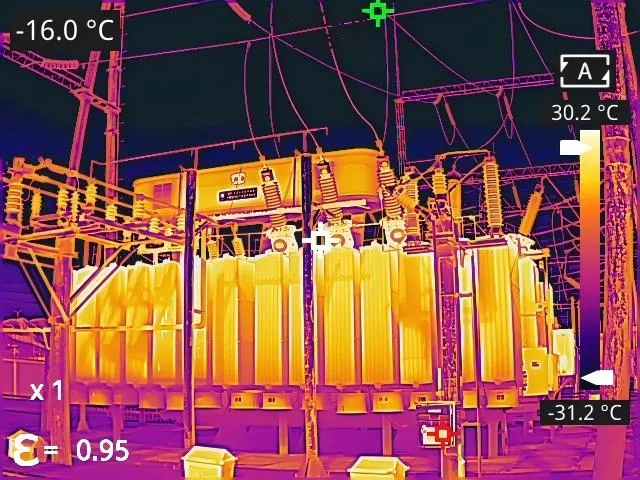
Transformers are among the most critical components of the power grid, responsible for energy transmission and voltage conversion. A transformer consists of the main body, cooling system, tap changers, protection devices (such as gas relays, oil conservators, and temperature sensors), and electrical bushings.Infrared thermal imaging enables effective fault detection during energized operation, revealing various defects in transformer tanks, oil conservators, bushings, and cooling circuits.
The transformer’s main body consists of the iron core, windings, oil tank, and insulating oil. While internal defects are difficult to detect due to the large size and internal oil circulation, a thermal imaging camera for electrical inspections effectively identifies defects that generate heat, such as magnetic leakage.

2) Transformer Bushing Fault Detection
Transformer bushings route the high- and low-voltage leads from inside the transformer to the exterior of the oil tank. They not only provide insulation between the leads and ground but also secure the leads and carry the load current over extended periods. Common bushing designs include capacitor, oil-filled, and porcelain types, each with different structural characteristics.
Capacitive bushings, which contain conductive rods, capacitor screens, insulating oil, and outer porcelain sleeves, predominate in transformers rated 35kV and above. They also experience higher failure rates. Thermal camera electrical inspections can easily detect thermal abnormalities indicating imminent failure, which are caused by defects such as bushing oil depletion and excessive dielectric loss.


3) Current Transformer (CT) Fault Detection
Current transformers (CTs) perform a critical function: they convert high-voltage, high-current primary signals into manageable low-voltage, low-current secondary signals that link the primary and secondary systems. These devices exist in large numbers throughout power networks, and their performance directly determines overall power reliability.
CTs can be classified by insulation medium into oil-filled, SF6 gas-insulated, and solid-insulated (for voltage levels of 35kV and below) types. The widely used oil-filled CT typically consists of primary conductive circuits, capacitor screens, insulating oil, secondary windings, and porcelain housings. Using a thermal imaging camera for electrical inspections enables the early identification of both current-induced thermal defects due to overheating at terminals and voltage-induced thermal defects due to excessive dielectric loss. Curve drawing based on historical data can display the changing trend of device temperature, providing intuitive and reliable data for the evaluation of device operating status.

4) Voltage Transformer (VT) Fault Detection
Voltage transformers (VTs), also referred to as potential transformers (PTs) connect primary and secondary systems by stepping down high-voltage grid signals. Two primary designs exist: electromagnetic and capacitive types. Capacitor-type voltage transformers are widely deployed in 110kV+ systems with solidly grounded neutral points, consisting of capacitor voltage divider assemblies and electromagnetic units. Thermal camera electrical inspections effectively identify voltage-induced thermal defects, including those due to partial discharge.

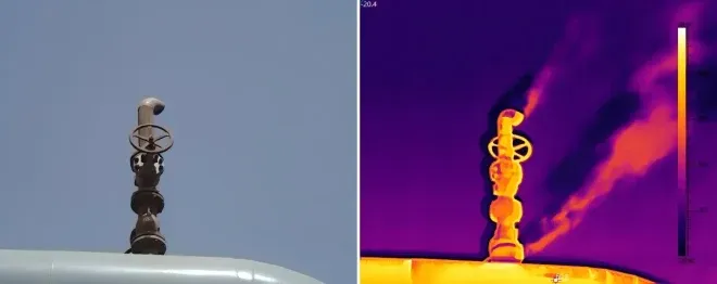
5) SF₆ Gas Leakage Detection
SF6 gas is the most commonly used insulating gas in high-voltage devices such as transformers, bushings, circuit breakers, current transformers, and GIS. These are critical components within substations, and any malfunction can significantly disrupt the normal operation of the power grid, leading to damage to circuit equipment.
Traditional methods for SF6 gas leakage detection, such as sniffers and soap solution tests, can detect the presence of SF6 gas but fail to accurately locate the leakage points. Worse still, they can be complex to operate and inefficient.
The handheld infrared gas thermal camera, based on the uncooled VOX detector featuring high spatial resolution and high sensitivity, can visualize gases for inspectors to accurately and remotely detect gas leakage points and scale in real time without the need to shut down the device. The visual images significantly reduce the complexity of SF6 leakage detection and improve detection accuracy and efficiency, minimizing the losses caused by leakage.


6) Circuit Breaker Fault Detection
Circuit breakers are among the most critical devices in electrical systems. They are designed to interrupt normal currents and clear short-circuit faults under fault conditions, directly affecting the reliability and safety of the entire power grid. Depending on the arc-extinguishing medium, circuit breakers can be SF6, oil, or vacuum types. Among them, SF6 circuit breakers typically consist of the main tank, grading capacitors, operating mechanisms, and control circuits. The defects identified through thermal camera electrical inspections are generally current-induced thermal defects.
Post-type circuit breakers comprise an arc chamber, support insulators, and mechanical drive assemblies. Thermal camera electrical inspections can detect thermal abnormalities in the arc chamber’s conductive elements, including: ① external contact overheating concentrated around terminal boards (usually from loose bolts or surface oxidation causing poor contact); ② abnormal arc chamber end temperatures focused on top caps or bottom flanges (usually from moving or stationary contact defects); ③ localized porcelain sleeve surface heating with small temperature differences relative to normal areas (typically from surface contamination or insulator cracks); and ④ elevated current transformer temperatures (typically from open or loose secondary circuits).


7) Gas-Insulated Switchgear (GIS) Fault Detection
Gas-Insulated Switchgear (GIS) packages all high-voltage electrical components (except transformers) according to the main wiring sequence within a metal enclosure filled with SF6 gas as insulation. It can be further classified into GIS and HGIS based on structural characteristics. Compact and reliable, these systems require minimal maintenance.
Thermal camera electrical inspections can identify current-induced thermal defects, such as localized overheating in certain conductive circuits of GIS: Overheating generated due to surface contamination of GIS lead-out bushings and contact at terminal connections. The eddy current losses in wall bushings represent comprehensive thermal defects. Parallel comparison of temperature across three phases can be used to comprehensively assess whether there is any abnormal temperature rise.


8) Knife Switch Fault Detection
Knife switches consist of a conductive circuit, insulators, and an operating mechanism. They are used in high-voltage systems to isolate equipment for maintenance or to change the system configurations. Their design with multiple contact points and frequent operation can lead to overheating, especially current-related thermal defects, as demonstrated through thermal camera electrical inspections.
Conductive circuits of knife switches mount on bases via post insulators, incorporating movable contacts and conductive rods driven by operating porcelain bottles, along with stationary contacts and terminal connections. Common detected issues include stationary contact temperatures exceeding 130°C in 220kV units (indicating poor contact), and phase-to-phase terminal board temperature differences above 15K in 110kV designs (indicating terminal bolt oxidation and loosening).
Additionally, the knife switch has multiple conductive connection points, leading to unstable contact resistance under current flow, which results in thermal defects. The main issues with post insulators include overheating due to surface contamination and insulator cracks. These issues can all be accurately detected using a thermal imaging camera for electrical inspections.


9) Lightning Arresters Fault Detection
Lightning arresters are widely used to limit operating overvoltage and lightning overvoltage in the power system. Most modern grids use metal oxide lightning arresters. During operation, lightning arresters often experience device failures due to internal moisture ingress caused by manufacturing defects. Thermal camera electrical inspections can help identify such hazards early on. The thermal defects of lightning arresters are typical voltage-induced ones.


10) Transmission Equipment Defect Diagnosis
Transmission lines primarily consist of foundations, towers, conductors, lightning arresters, insulators, hardware fittings, and grounding devices. Infrared thermal imaging can detect thermal anomalies caused by issues like degraded insulators and corroded fittings. Common hazards include:
- Insulators: degradation, contamination, or cracking, which may reduce insulation and cause line tripping due to flashover.
- Ground wires: poor contact between compression sleeves and conductors, leading to overheating and potential line breaks.
- Hardware fittings: loose bolts, poor crimping, or conductor strand breakage causing localized overheating, threatening line stability.
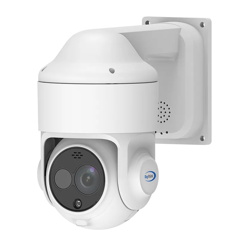
Thermal camera electrical inspections deploy dual-spectrum PTZ cameras for 360° autonomous patrols, supplemented by handheld thermal imaging cameras for on-site inspections. The system achieves continuous monitoring of critical components of transmission equipment, which includes real-time insulator condition assessment, clamp integrity verification, and cable terminal inspection, delivering high-temperature alerts and precise fault localization in real time to protect transmission line operational safety.


11) Power Cable Temperature Monitoring
Power cables transmit electrical energy through conductors enclosed in insulation layers, shielding, filling materials, inner protective layers, and armor layers. They can be classified by the type of insulation, for example, oil-impregnated paper, plastic, and rubber. Thermal camera electrical inspections detect both current-induced thermal defects due to overheating at terminals and voltage-induced thermal defects due to dampness.
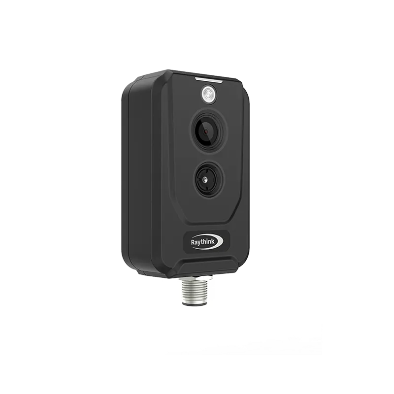
A thermal imaging camera for electrical inspections, especially the thermographic cube camera featuring a compact structure, can monitor in real time cables in ducts, where the space is confined. It can be deployed at multiple monitoring points to monitor the temperature changes of cables in cable trenches in real time and provide multi-level high-temperature alarms to intuitively and effectively reduce the probability of incidents and notify the operation and maintenance personnel in advance for troubleshooting.

3. Advantages of Thermal Imaging Camera for Electrical Inspections
1) Non-Contact Operation and Safety
Infrared thermal imaging operates through passive, non-contact detection. Equipment is diagnosed through remote observation without physical contact, sampling, or service interruption. A thermal imaging camera for electrical inspections delivers inherent accuracy and speed advantages, and enables real-time online monitoring and fault diagnosis without disrupting normal operations.
2) Intuitive Visualization and Precise Fault Identification
Infrared thermal imaging resists electromagnetic interference while accurately tracking thermal targets remotely. Temperature fields become immediately visible and high-temperature hazard points are automatically captured, presenting failure locations intuitively. This enables qualitative and quantitative assessment of defect nature, position, and severity.
3) Predictive Maintenance Through Trend Analysis
Regular equipment temperature collection through thermal camera electrical inspections produces visual trend graphs. This data-driven approach forms institutional knowledge about equipment operation patterns and risk points, supporting informed maintenance planning, fault prediction, and defect analysis. Early discovery, early warning, and early repair thus become achievable.
4. Application Cases of Thermal Camera Electrical Inspections
1) Case Study – Boiler Outer Wall Monitoring
In the process of thermal power generation, the boiler is one of the most critical facilities and is key to achieving full power generation.
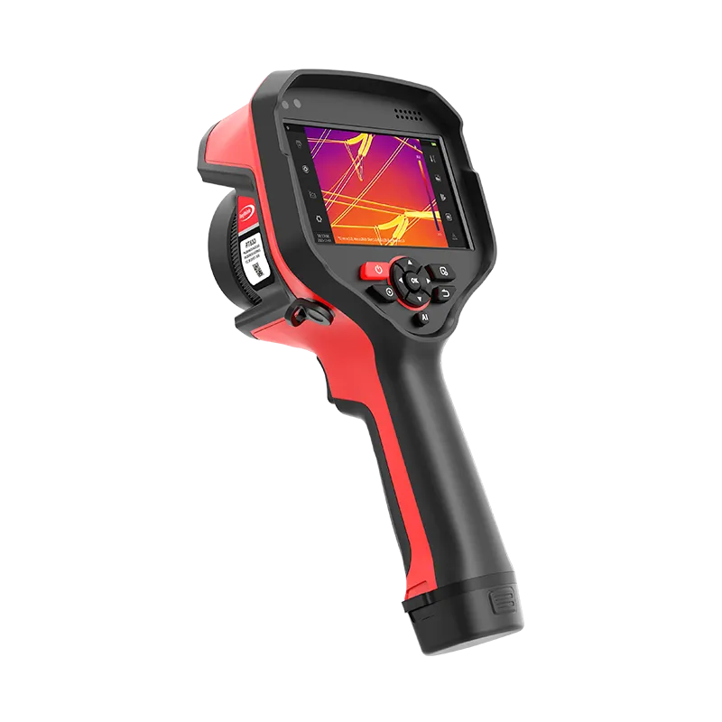
Raythink solution: The ATR31/61 motorized focusing thermal camera can be employed to monitor the boiler outer wall in real time. It detects localized “hot spots” on the wall to assess the boiler’s health status and timely detect wear, providing a visual reference for maintenance.
Result: Early hot spot detection enables planned maintenance before catastrophic equipment failure, preventing service disruptions and reducing maintenance costs through condition-based scheduling rather than fixed calendars.

2) Case Study – Generator Carbon Brush and Slip Ring Monitoring
There is a risk of fire hazards associated with the slip ring and carbon brush during the normal operation of the generator. The main issues related to the carbon brush include poor quality, excessive resistance, incorrect selection, impurities on the contact surface, and poor contact; for the slip ring, the primary issues are surface burning and poor surface finish; other contributing factors include improper adjustment methods, unfavorable on-site conditions, anode evaporation, and cathode powdering.
Raythink solution: The compact cube camera can be selected for real-time temperature monitoring of the carbon brush and slip ring, allowing for alarms on abnormal points and assisting inspectors in troubleshooting.
Result: Continuous thermal monitoring prevents carbon brush and slip ring fires, enabling scheduled maintenance before problems escalate into equipment failure requiring generator shutdown.

3) Case Study – Photovoltaic Panel Hot Spot Detection
Solar panels can develop hot spots due to breakage, micro-cracks, poor welding, as well as partial surface shading, acid rain, bird droppings, dust, site conditions, and air pollution.
Raythink solution: Online light type PTZ camera combined with RT series pro-grade thermal camera enables real-time detection of temperature distribution within PV panels and generation of clear and intuitive thermal images, helping users quickly and accurately locate the hot spot positions on solar panels.
Result: Early hot spot detection prevents panel degradation and potential fire incidents, maintaining renewable energy generation efficiency and protecting infrastructure investment.


4) Case Study – Wind Turbine Cable Condition Management
When a wind turbine yaws, the main cable will be twisted, and the main cable and optical fiber may be damaged if the cable twist protection device is faulty. At the same time, oil stains, fluff, or foreign matter on cable contacts, and aging of the outer surface, can pose a risk. Particularly in the case of twisted cables, if they are tangled, the cables in the middle have no cooling space, which may lead to overheating and affect the safe operation of the main cable.
Raythink solution: The online cube camera is used to continuously monitor cables’ temperature status during operation for 24 hours. This allows for visual location of high-temperature hazards and timely detection of excessively high temperatures, preventing uncontrolled heat buildup that could lead to cable faults. Additionally, the handheld routine inspection device is used to regularly perform manual inspections for verification and inspection of high-temperature cable alarms and temperature monitoring, allowing for timely preventive maintenance.
Result: Early thermal alerts identify twisted cable areas developing dangerous temperatures before visible damage appears. Scheduled preventive maintenance eliminates cable failures that would force turbine shutdown, reducing cable-related downtime and extending cable life through early intervention.


5. Best Thermal Imaging Camera For Electrical Inspections from Raythink


6. Conclusion
Infrared thermal imaging has become indispensable for modern electrical inspections. By providing non-contact, real-time visualization of temperature anomalies around the clock, it empowers maintenance teams to identify faults early and enhance safety. Choosing the best thermal imaging camera for electrical inspections means choosing a smarter and safer way to manage power infrastructure.
Through systematic thermal camera electrical inspections, organizations establish equipment temperature baselines that enable trend analysis and predictive maintenance programming, thereby shifting from reactive repair to proactive prevention.
Raythink delivers complete infrared thermal imaging solutions for power industry applications. Contact our technical team to develop customized solutions addressing your specific inspection challenges.