Since the global adoption of sustainable development concepts, many countries have implemented energy conservation and emission reduction policies, actively promoting the construction industry toward green, low-carbon, and sustainable development. A series of standards for energy-efficient building design, acceptance, products, and inspection methods has been introduced to strictly control building energy consumption and reduce greenhouse gas emissions. This trend reflects governments’ strong emphasis on building energy efficiency and has driven continuous innovation in energy-saving technologies and inspection methods.
Challenges in Traditional Building Inspection
However, as buildings grow in scale, various factors such as design, construction, and usage often lead to issues like hollowing of exterior walls, water leakage, and poor air tightness. These defects can compromise structural stability and even pose safety risks. Traditional inspection methods are time-consuming and inefficient. They typically identify only surface-level or large-scale issues and often fail to identify hidden problems promptly, leaving them unnoticed until significant damage occurs, resulting in costly remediation.
Infrared Thermal Imaging: A Solution for Efficient Building Inspection
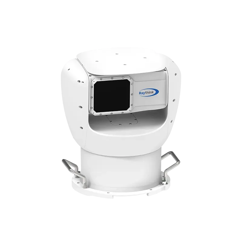
Infrared thermal imaging technology serves as a pre-maintenance diagnostic tool that enables accurate, non-contact inspection of rooftops, ceilings, walls, and floors, including concealed areas that are difficult for personnel to access. By visually displaying the temperature distribution of a building through thermal images, infrared thermal imaging enables the efficient inspection of energy loss, hidden defects, and potential safety hazards. It provides a cost-effective, efficient, and non-destructive inspection solution that helps enhance both energy efficiency and structural safety in buildings.
Thermal Imaging Applications for Building Inspection
1. Inspection of Hollowing and Adhesion Defects in Exterior Wall Finishes
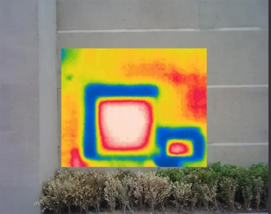
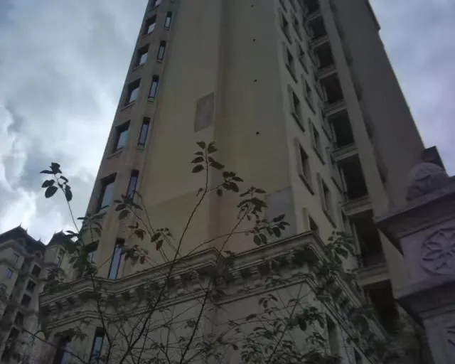
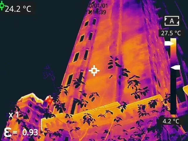
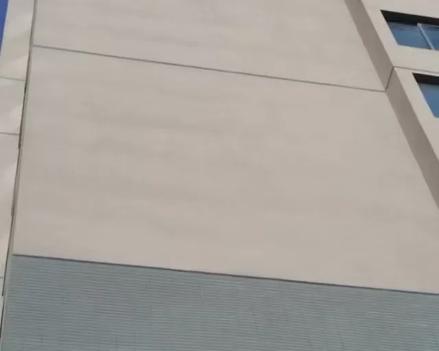
With the widespread use of facing bricks for aesthetic enhancement, the quality of exterior wall finishes has drawn increasing attention. Incidents of brick detachment from façades occur from time to time, posing risks to both personal safety and property. When hollowing occurs in exterior wall finishes (bricks or panels), an air layer forms at the hollowed area. Since air is a poor conductor of heat, it obstructs thermal transfer. As a result, the thermal conductivity between the wall surface and the main structure is significantly reduced.
On sunny days with strong sunlight, the temperature of the hollowed area is higher than that of intact wall sections, appearing as distinct “hot spots” on the thermal camera. Under low sunlight or cooler conditions, the hollowed area has a lower temperature and appears as “cold spots” on the thermal camera. By analyzing thermal images, inspectors can quickly locate bonding defects such as detachment or hollowing, effectively preventing safety hazards.
To ensure inspection accuracy, infrared thermal imaging inspection of exterior wall-facing bricks should be conducted in dry conditions with low wind speeds. During the inspection, factors such as the building’s azimuth, sunlight exposure, and surrounding environment should be taken into account to determine the optimal time for imaging. The appropriate shooting position should be selected based on the building’s height and width, and it is essential to assess whether nearby objects may affect the wall surface. If necessary, shielding measures should be taken or indoor radiation sources should be turned off. When inspecting, it is recommended to begin with a general scan of the building’s exterior finishes. Once suspicious areas are identified, a detailed inspection of those specific areas should follow to ensure early inspection and timely remediation of potential issues.
2. Inspection of Insulation Layer Defects
Defects and damage within the exterior wall insulation layer of a building present distinct temperature patterns in infrared thermal images. When heat flows into a building, if the underlying structure is homogeneous, the heat will distribute uniformly and reflect evenly, resulting in a consistent surface temperature field.
However, if there are thermal insulation defects inside the building, heat will accumulate in the defective areas, causing a localized temperature rise. These areas appear as prominent “hot spots” in thermal images. In contrast, if there are thermal conductivity defects, the heat transfers more easily through these regions, leading to noticeably lower surface temperatures, which appear as clear “cold spots” in the thermal image. Thus, infrared thermal imaging technology enables clear and intuitive inspection of surface and near-surface defects and damage in the building.
When conducting a thermal defect inspection of the exterior wall insulation layer, it is recommended to begin with a general scan from the exterior. If anomalies are inspected, a more detailed inspection should be carried out on both interior and exterior surfaces. Outdoor inspections should ideally be conducted on overcast days or at night to avoid direct solar radiation; for indoor inspections, heat sources such as air conditioners should be turned off to ensure accurate results. These careful inspection practices help effectively identify and locate thermal defects in exterior walls and proactively prevent potential structural safety issues.
3. Leakage and Moisture Inspection
When the roofing waterproofing layer fails and minor cracks in walls lead to rainwater leakage, indoor heat diffusion, solar radiation absorption, and conduction cause temperature distribution differences between the leakage area and its surroundings. Infrared technology can therefore be used to analyze and determine the source of the leakage.
Choosing an appropriate time for inspection is essential to accurately identify the leakage path. The leakage gaps must be filled with water while areas outside the gaps remain relatively dry. It is advisable to perform the inspection under the following conditions:
- After the rain: The optimal time is within 24 hours after rainfall when the building surface is relatively dry yet moisture remains in the leakage area.
- On sunny days: Water can be sprayed on suspected leakage areas to simulate rainfall, ensuring that the leakage source and its path are filled with water.
Inspection Procedure
After rain or a water test, begin by scanning a large area of the exterior wall or roof surface with infrared thermal imaging. Identify any low-temperature zones as suspicious areas. Then, carry out a corresponding scan of the interior to pinpoint the leak location.
Precautions
When anomalies appear in the thermal images, first rule out interference from any heat or cold sources. Confirm the leakage situation by comparing the measured thermal images with the expected temperature distribution for that area or by using other inspection methods. If there is any dispute regarding the on-site infrared imaging results, local destructive testing can be used for further verification.
4. Air Tightness Inspection for Buildings
Poor air tightness of buildings will cause problems such as cold air pumping into the room, heat leakage, and increased load of the heating system. Thermal cameras can be used to check key parts and provide an effective qualitative analysis basis for inspection.
A common method for inspecting air leaks involves measuring the air exchange rate through a process known as the blower door test. In this procedure, negative pressure is created inside the building. As a result, the outdoor pressure becomes higher than the indoor pressure, causing air to infiltrate through gaps. At these leakage points, convective airflow occurs, leading to temperature variations on window and door surfaces compared to the surrounding areas. Infrared thermal imaging takes advantage of this phenomenon by capturing thermal images of doors and windows both before and during the inspection. By comparing these images, it is possible to visually identify airtightness defects across the entire tested window or door. This allows for targeted repair or reinforcement of defective or vulnerable areas.
Precautions
Infrared inspections should always be performed on the negative pressure side of the building. There must be a temperature and pressure difference across the building envelope when using thermal cameras to inspect air leakage. To ensure accurate results, the exterior surfaces should not be exposed to direct sunlight for at least 12 hours before the inspection, and the interior surfaces should be free from direct illumination by artificial light. Avoid conducting the inspection when surface areas are exposed to direct heat sources. If radiators are present nearby, they should be turned off and the area allowed to cool for at least 24 hours before testing.
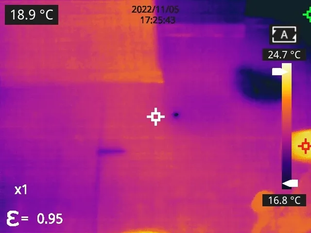
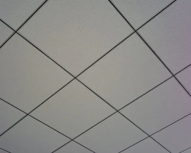
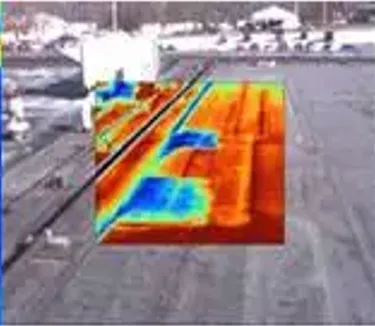
5. Roof Insulation Layer Inspection
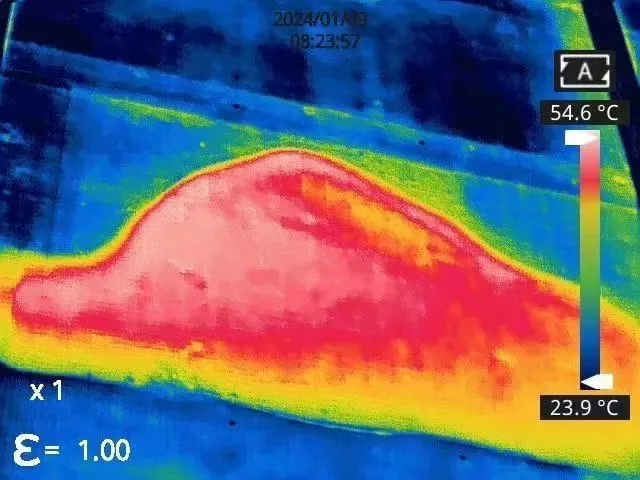
Roof waterproofing materials have different thermal expansion properties compared to the underlying concrete. Under continuous cycles of thermal expansion and contraction, shear stress repeatedly occurs between the layers. Since waterproofing materials are typically organic, they gradually deteriorate under sunlight and ultraviolet radiation, leading to a progressive decline in adhesive strength.
When the adhesive strength weakens and becomes less than the tensile stress caused by expansion and contraction, the waterproof layer begins to detach from the concrete, creating voids. As the delaminated area continues to expand, the voids grow larger. Eventually, when the waterproof material has aged to a certain extent and its adhesive force drops to zero, surface cracking occurs, and the space between the waterproof layer and the concrete roof begins to retain water, which is difficult to evaporate. At this stage, the waterproofing layer is no longer effective. When the accumulated water and rainwater reach a certain pressure, they may seep through cracks in the roof.
The heat capacity of a normal roof area differs from that of a moisture-laden area after leakage. Therefore, when the ambient temperature changes, the rate of temperature change will vary between damaged and undamaged areas, resulting in detectable surface temperature differences.
Thermal cameras can be used to inspect temperature distribution on the roof, allowing the identification of issues such as waterproofing layer leakage or missing insulation layers. This enables timely and effective inspection of roof leaks, thereby protecting indoor devices, products, and materials from potential water damage.
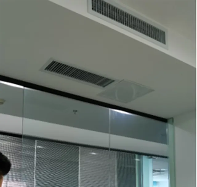
6. Air Conditioner Fault Inspection
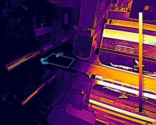
Air conditioner repair requires quickly and accurately identifying fault points to enable timely fixes. Traditional repair methods often involve disassembling air conditioner components to locate faults, which is both time-consuming and labor-intensive. Infrared thermal imaging technology, by detecting temperature differences in heat sources and converting them into visible thermal images, offers a timely, efficient, accurate, and intuitive solution. During air conditioning system detection, infrared thermal imaging can help maintenance personnel promptly and precisely locate hidden issues or fault points in both indoor and outdoor units of the air conditioner, thereby improving repair efficiency and accuracy.
When the cooling performance of an air conditioner is suboptimal, thermal cameras can be used to inspect the temperature distribution of key components such as the compressor, condenser, and evaporator. By comparing the temperature distribution under normal operating conditions, it is possible to determine which components are malfunctioning or underperforming. For example, if the compressor exhibits an uneven temperature distribution, it may be caused by internal mechanical faults or electrical malfunctions within the compressor. If the condenser exhibits an uneven temperature distribution, it could be due to internal pipe blockages or damage to the heat-dissipating fins. If the evaporator shows an uneven temperature distribution, it may result from internal pipe blockages or insufficient refrigerant.
In addition to inspecting the temperature distribution of both the indoor and outdoor units of the air conditioner, thermal cameras can also be used to inspect heat leakage in components such as air conditioning pipes and air outlets. If there is heat leakage at pipes, joints, or other parts, it can lead to poor cooling performance or even complete cooling failure. By using thermal cameras to inspect such heat leakage on time, problems can be identified and addressed promptly, thereby improving the cooling efficiency of the air conditioner.
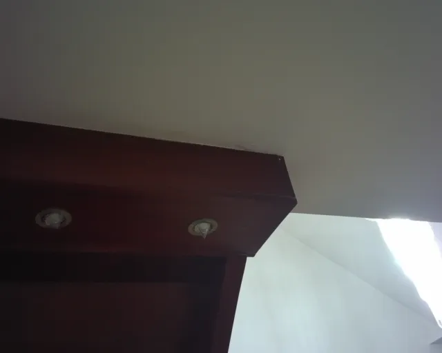
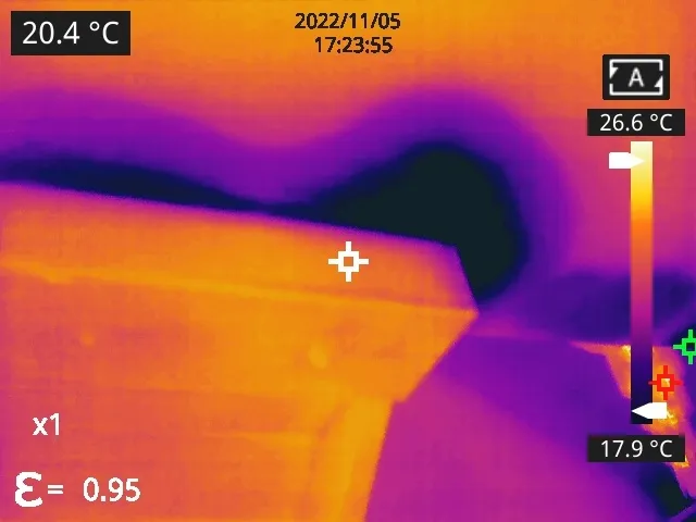
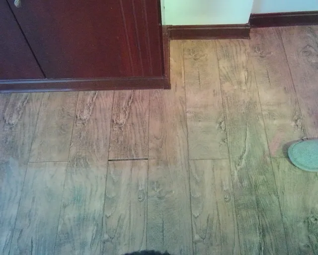
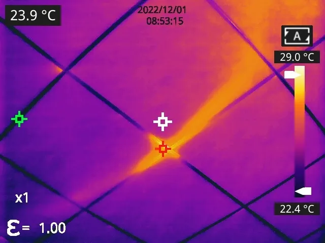
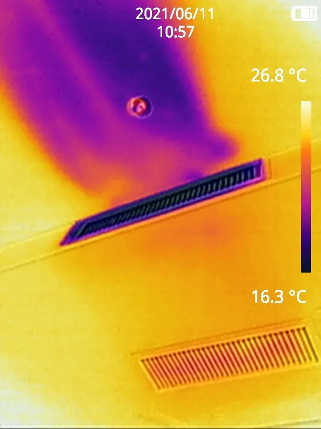
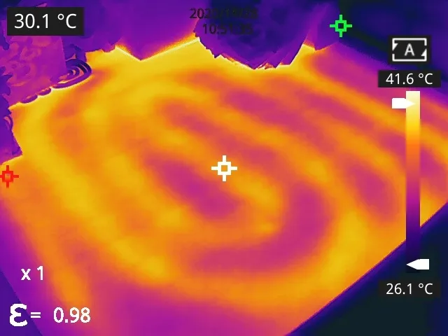
7. Underfloor Heating and Manifold Inspection
Common underfloor heating systems fall into two categories: electric underfloor heating and hydronic (water-based) underfloor heating. Typical issues include uneven heating, lack of heat, or water leakage from the heating pipes. While underfloor heating systems provide both warmth and aesthetic appeal, they have long presented challenges in terms of repair. Since the pipes are installed beneath the floor finish, troubleshooting becomes difficult. Key concerns include how to accurately locate leakage points, identify pipe routing, and diagnose and repair faults with minimal damage to the existing interior decoration—factors that are critical to improving service efficiency.
Hydronic Heating Systems
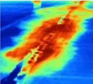
In hydronic heating systems, the traditional method for checking if the underfloor pipes are leaking involves pressurizing each circuit and observing pressure drops to determine if leakage is present. However, this approach first requires locating the abnormal area, which adds significant difficulty to the repair process. In contrast, a thermal camera can be used to quickly locate abnormal areas in hydronic heating systems.
Electric Underfloor Heating Systems
In electric underfloor heating systems, the heating cables are high-resistance linear heating elements. Typically, a single cable is laid in series for each room. These cables are prone to aging and develop linear heating issues over time. Since the system is connected in series, a fault in any section can lead to the failure of the entire system’s heating. Therefore, regular maintenance and inspection of electric heating systems is critically important. Thermal cameras offer a fast and efficient method for maintenance and inspection.
Using thermal cameras for HVAC pipeline inspection is a non-destructive method that allows for quick identification of pipe routing and heat transfer status. It eliminates the need for excessive labor and cost while enabling precise inspection. By analyzing the thermal images and using markers to locate suspected leak points, maintenance personnel can perform repairs at the lowest cost and with minimal disruption to the user’s living environment.
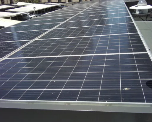
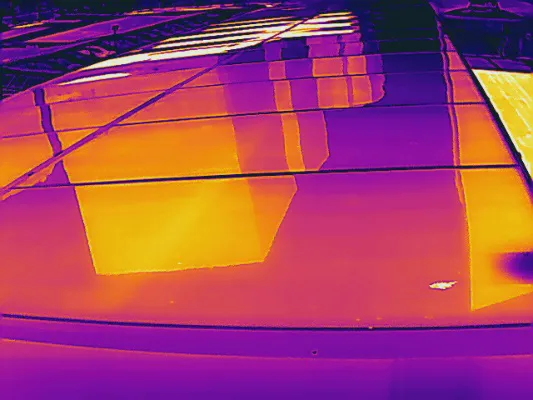
During the manufacturing and testing processes, solar cell modules may experience issues such as microcracks, debris, poor welding, etc. Alternatively, during operation, they may be blocked by other objects for extended periods. The solar cells under shading conditions will overheat significantly, resulting in the “hot spot effect,” which can cause severe damage to the solar cells.
By using thermal cameras to inspect the heating conditions of each cell on the module, the temperature distribution of the cells can be monitored in real time to check for uniformity. Fault points can be identified, and the hot spot locations can be accurately pinpointed.
Under normal conditions, the temperature distribution of each cell is uniform. However, if individual cells within the module matrix exhibit unusually high temperatures, it indicates a potential issue with the cell. The cell has shifted from its normal energy conversion status (from light energy to electrical energy) to a status where it is consuming electrical energy and producing heat, which affects the overall power conversion efficiency of the module. In this case, the over-temperature cell needs to be replaced. Thermal cameras support secondary analysis, allowing customers to conduct flexible secondary analysis as needed. This includes tracking the shape changes of each panel, recording periodic temperature variations, and documenting the cyclic degradation of materials.
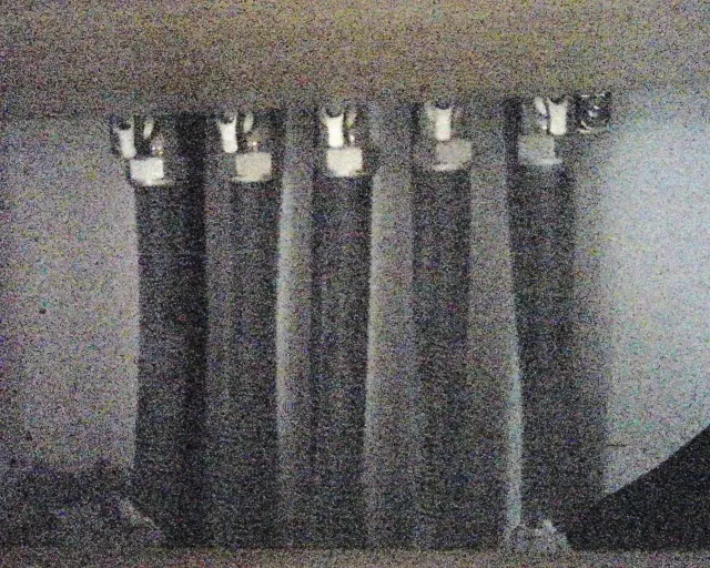
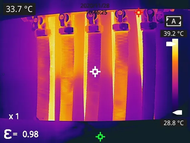
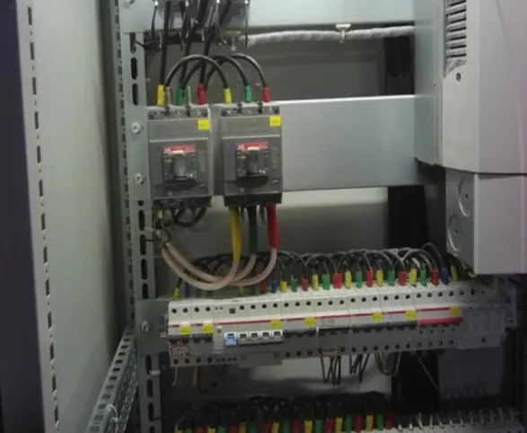
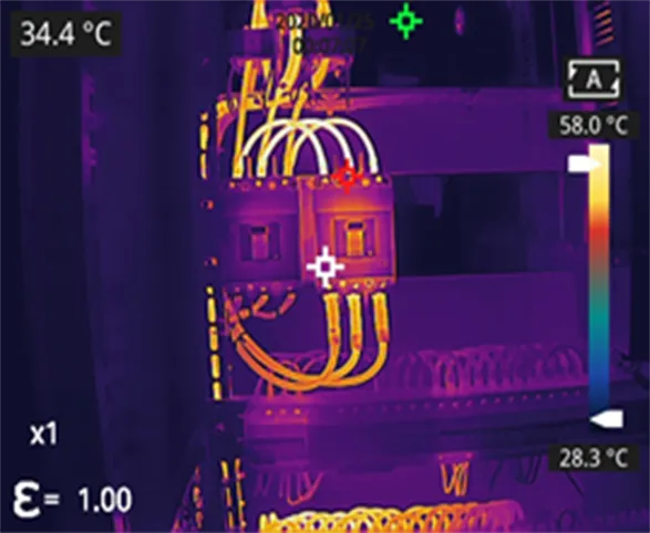
As the temperature drops, the electricity demand of businesses and communities increases. The normal operation of power supply devices and electrical devices in distribution rooms directly affects the production operations in industrial parks and the daily lives of residents. Once a fault occurs, it may result in power failure, voltage instability, and other electrical accidents. Thermal cameras can timely discover thermal defects and hidden thermal dangers of electrical devices, thus preventing line thermal accidents and ensuring the security of electricity in winter.
By placing infrared thermal cameras within the key electrical cabinets in data center rooms, critical components such as electrical contacts, switches, and junctions can be monitored 24/7. If abnormal heating occurs due to overload or poor contact, the system will immediately issue an alarm, ensuring that risks are dealt with promptly and devices continue to operate safely.
Advantages of Thermal Imaging for Building Inspection
The thermal capacity of a building’s normal components differs from that of damaged areas. As a result, when environmental temperatures change, the temperature change between damaged and normal areas will differ. Thermal cameras visualize the temperature distribution of objects with high sensitivity, quick inspection, and no need for additional lighting, which allows for accurate identification of abnormal areas in buildings. This improves the accuracy, effectiveness, and rationality of inspections, making non-destructive testing of buildings more scientific and practical. Additionally, the device is lightweight and portable, making it an ideal tool for building inspections.
- Non-contact and long-distance inspection: No need to damage the building structure or set up scaffolding.
- Fast and comprehensive inspection: Capable of quickly and thoroughly scanning buildings in real-time, ensuring no area is missed.
- Visual and intuitive results: The two-dimensional infrared thermal images visually display the temperature field at each point on the object, accurately locating defect locations and showing the size of defect areas.
- Intelligent temperature analysis software: Full-featured software makes it easy to perform further temperature analysis on images via a computer.
- Precise measurements: Input information such as target distance, target emissivity, and ambient temperature to automatically calculate and correct the influence of atmospheric transmissivity and target surface emissivity on measurement results.


.webp)

.webp)
